- 您现在的位置:买卖IC网 > Sheet目录861 > GCM188R71E154KA37D (Murata Electronics North America)CAP CER 0.15UF 25V 10% X7R 0603
�� �
�
�!� Note� ?� Please� read� rating� and� !� CAUTION� (for� storage,� operating,� rating,� soldering,� mounting� and� handling)� in� this� catalog� to� prevent� smoking� and/or� burning,� etc.�
�?� This� catalog� has� only� typical� speci?cations.� Therefore,� please� approve� our� product� speci?cations� or� transact� the� approval� sheet� for� product� speci?cations� before� ordering.�
�!� Caution�
�Continued� from� the� preceding� page.�
�4-4.� Leaded� Component� Insertion�
�1.� If� the� PCB� is� flexed� when� leaded� components� (such� as�
�transformers� and� ICs)� are� being� mounted,� chips� may�
�crack� and� solder� joints� may� break.�
�Before� mounting� leaded� components,� support� the� PCB�
�using� backup� pins� or� special� jigs� to� prevent� warping.�
�5.� Washing�
�Excessive� ultrasonic� oscillation� during� cleaning� can� cause�
�the� PCBs� to� resonate,� resulting� in� cracked� chips� or� broken�
�solder� joints.� Take� note� not� to� vibrate� PCBs.�
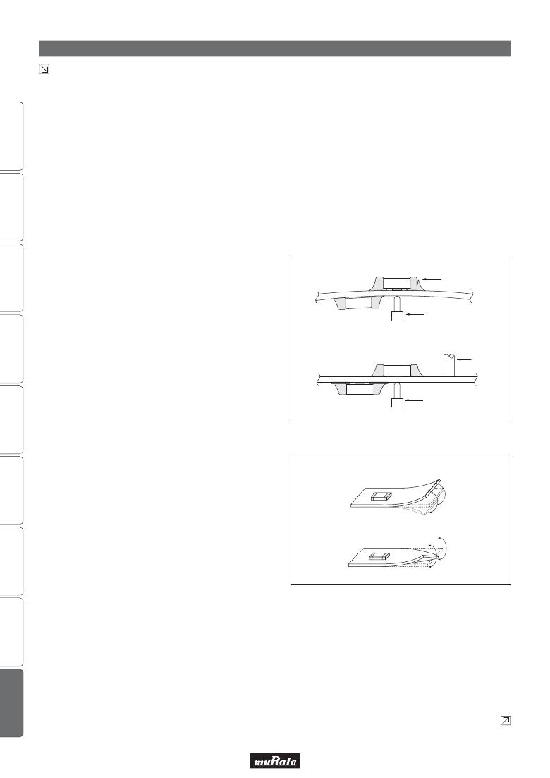
�6.� Electrical� Test� on� Printed� Circuit� Board�
�1.� Confirm� position� of� the� support� pin� or� specific� jig,� when�
�C03E.pdf�
�May.17,2013�
�inspecting� the� electrical� performance� of� a� capacitor� after�
�mounting� on� the� printed� circuit� board.�
�1-1.� Avoid� bending� the� printed� circuit� board� by� the�
�pressure� of� a� test� pin,� etc.�
�The� thrusting� force� of� the� test� probe� can� flex� the� PCB,�
�resulting� in� cracked� chips� or� open� solder� joints.�
�Provide� support� pins� on� the� back� side� of� the� PCB� to�
�prevent� warping� or� flexing.�
�1-2.� Avoid� vibration� of� the� board� by� shock� when� a� test� pin�
�[Not� Recommended]�
�[Recommended]�
�Peeling�
�Test-pin�
�Support� Pin�
�contacts� a� printed� circuit� board.�
�Test-pin�
�7.� Printed� Circuit� Board� Cropping�
�1.� After� mounting� a� capacitor� on� a� printed� circuit� board,� do�
�not� apply� any� stress� to� the� capacitor� that� is� caused� by�
�[Bending]�
�bending� or� twisting� the� board.�
�1-1.� In� cropping� the� board,� the� stress� as� shown� at� right�
�may� cause� the� capacitor� to� crack.�
�Avoid� this� type� of� stress� to� a� capacitor.�
�[Twisting]�
�Continued� on� the� following� page.�
�54�
�发布紧急采购,3分钟左右您将得到回复。
相关PDF资料
GCM31A7U2J471JX01D
CAP CER 470PF 630V 5% U2J 1206
GCM31C5C1H104JA16L
CAP CER 0.1UF 50V 5% NP0 1206
GHF459601ZA6N
CAP ARRAY 6CH 600PF 50V 1404
GL2L5LS050D-T1-C
DELAY LINE 0.5NS +-50PS 16SOIC
GL6R0KA7B200
INDUCTOR BROADBAND 6UH
GP447
CAP CER 47PF 1KV 10% RADIAL
GRF4.0419.013.C
GRF4 APPLIANCE INLET FILTER 15A
GRM022R60J332KE19D
CAP CER 3300PF 6.3V X5R 01005
相关代理商/技术参数
GCM188R71E154KA37J
功能描述:多层陶瓷电容器MLCC - SMD/SMT 0.15uF 25Volts X7R 0.1
RoHS:否 制造商:American Technical Ceramics (ATC) 电容:10 pF 容差:1 % 电压额定值:250 V 温度系数/代码:C0G (NP0) 外壳代码 - in:0505 外壳代码 - mm:1414 工作温度范围:- 55 C to + 125 C 产品:Low ESR MLCCs 封装:Reel
GCM188R71E222KA37D
功能描述:多层陶瓷电容器MLCC - SMD/SMT 0.0022uF 25Volts X7R 10%
RoHS:否 制造商:American Technical Ceramics (ATC) 电容:10 pF 容差:1 % 电压额定值:250 V 温度系数/代码:C0G (NP0) 外壳代码 - in:0505 外壳代码 - mm:1414 工作温度范围:- 55 C to + 125 C 产品:Low ESR MLCCs 封装:Reel
GCM188R71E223KA02D
功能描述:多层陶瓷电容器MLCC - SMD/SMT 0603 0.022uF 25volts X7R 10%
RoHS:否 制造商:American Technical Ceramics (ATC) 电容:10 pF 容差:1 % 电压额定值:250 V 温度系数/代码:C0G (NP0) 外壳代码 - in:0505 外壳代码 - mm:1414 工作温度范围:- 55 C to + 125 C 产品:Low ESR MLCCs 封装:Reel
GCM188R71E223KA02J
制造商:Murata Manufacturing Co Ltd 功能描述:
GCM188R71E223KA37D
功能描述:多层陶瓷电容器MLCC - SMD/SMT 0.022uF 25Volts X7R 0.1
RoHS:否 制造商:American Technical Ceramics (ATC) 电容:10 pF 容差:1 % 电压额定值:250 V 温度系数/代码:C0G (NP0) 外壳代码 - in:0505 外壳代码 - mm:1414 工作温度范围:- 55 C to + 125 C 产品:Low ESR MLCCs 封装:Reel
GCM188R71E223KA37J
功能描述:多层陶瓷电容器MLCC - SMD/SMT 0.022uF 25Volts X7R 0.1
RoHS:否 制造商:American Technical Ceramics (ATC) 电容:10 pF 容差:1 % 电压额定值:250 V 温度系数/代码:C0G (NP0) 外壳代码 - in:0505 外壳代码 - mm:1414 工作温度范围:- 55 C to + 125 C 产品:Low ESR MLCCs 封装:Reel
GCM188R71E224K
制造商:MURATA 制造商全称:Murata Manufacturing Co., Ltd. 功能描述:Chip Monolithic Ceramic Capacitor 0603 X7R 0.22μF 25V
GCM188R71E224KA55
制造商:MURATA 制造商全称:Murata Manufacturing Co., Ltd. 功能描述:Chip Monolithic Ceramic Capacitors for Automotive